At MBI, we’re always working on our equipment to make it more efficient, reliable and easy to use, and we do so through innovation. Our motivation and goal is to consistently improve your work tools for optimal results in minimal time.
We’ve talked about the Through The Bit Plug (TTB Plug) before when we first introduced it on the market. Normally, this type of product would require a shoe. Now, however, you no longer need to pull out the drill rod—this is a cementing-wedging plug that can simply and easily be installed directly through the core bit. What’s more, it can be used on any standard ID NQ or HQ bit. You’ll need a smooth core lifter case, along with a back-end adapter to direct the pump’s full flow through the inner tube. That said, today we’d like to show you how the TTB grouting plug assembly and demonstrate how to assemble and use it.
Gone are the days when you had to pull out your rod string to prepare your system to grout or wedge a hole, or do anything else to lock water into the borehole.
Wondering how the TTB Plug works? We’ll show you.
STEP 1
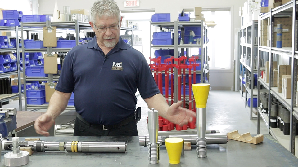
A SIMPLE SYSTEM
It’s a very simple system. Basically, you start out with a standard head assembly—the inner tube assembly you’re using for your normal drilling program. Now imagine you’re at the bottom of the hole and you must grout the hole for wedging or pull back to block an intake of water.
STEP 2
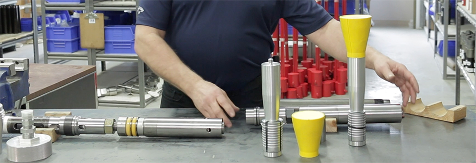
STARTING WITH YOUR STANDARD INNER TUBE
Take your standard inner tube assembly that you just finished your last run with and measure the operating length (measure and record the length from the end face of your core lifter case to the bottom contact edge of your landing shoulder, also take note of the length from your landing shoulder to the end face of your inner tube cap/connector). Now you are ready to add the TTB adapter to the bottom of the standard head assembly. All you have to do is remove the lower bearing assembly, complete with lower latch body, landing shoulder, landing indicator bushing and ball. Now take the TTB lower latch body adapter, and assemble with the TTB inner tube grouting adapter and adjust reset your head length to the landing shoulder and lock the assembly as you would a regular head (You match your operating length that you measured earlier). Place the landing indicator bushing and ball into the lower adapter and reconnect the assembly to your existing upper assembly and tighten. You add your inner tube (1.5 or 3 metres in length) or an extended barrel to that. Next, remove your core case and replace it with the smooth core lifter case provided in the TTB kit. This is a necessary part that provides a smooth transition of the TTB plug through your core bit. You now have your inner tube with the core case assembly and your upper head assembly with inner tube cap adapter. You are ready for the next step.
STEP 3
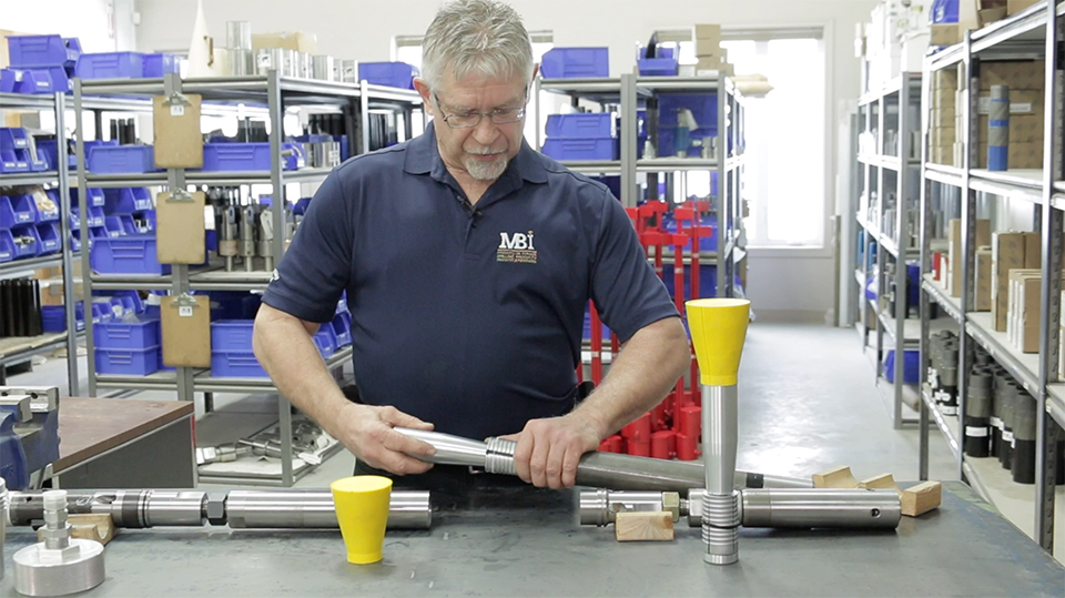
LOADING THE GROUTING SYSTEM PLUG
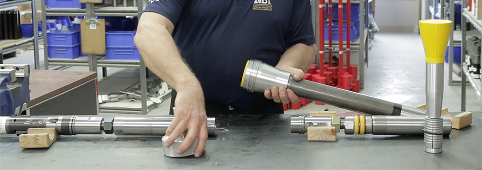
Now you need to load the plug system. Insert the grout plug grappler into your inner tube assembly, once inserted into the inner tube just past the grapple, carefully remove the zip tie to release the dogs. Do not push this assembly too far down into the tube as you will need to access it for the next step. Now take your adapter, which has a cone-shaped bore, and thread it onto your inner tube. (at this point you should still see the male threaded end of the grabble assembly protruding from inside the adapter. Now take the seal portion which has a female thread and thread it onto the end of your grapple and tighten snuggly by hand. Lubricating the seal with linseed oil or a similar biodegradable oil will allow it to slide through the loading chamber. You can now push the plug assembly firmly down into the cone adapter and connect the water adapter cap to close the loading chamber assembly.
STEP 4
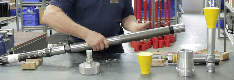
ADJUSTING YOUR LOADING ADAPTER FOR YOUR WATER FLOW
The next step is to adjust the loading adapter for your water flow to the head. Simply attach your water supply, using very slow, low pressure, and apply water pressure to the head. This will push the seal through the adapter, compressing it and putting it inside of your inner tube assembly. When the seal is compressed inside your inner tube and has reached the right point, water will start to jet out of the bleed hole through the side of the loading chamber. Once you see the jet of water, you’ll know that this step is complete.
STEP 5
TWO ASSEMBLIES
Once step 4 is complete, remove the loading chamber assembly from the inner tube. When you take the cap off, the seal will be inside of the tube. The grout plug assembly is now inside of the tube, but with the seal compressed inside. So now you have this assembly along with the grout plug inside the tube.
STEP 6
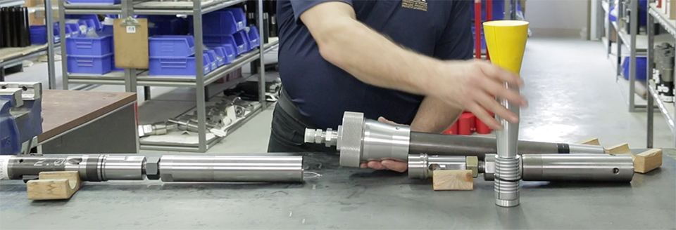
ATTACHING THE INNER TUBE CAP REPLACEMENT
You now take that assembly (the regular inner tube assembly with the grout tube assembled inside), attach it to your inner tube cap replacement, lock it all up and re-measure to make sure that the length is the same as it was for your last core assembly. Be sure to set your landing indicator ball before you lower the complete assembly down into your rod string, allowing normal descent time and pump-in cycle until the complete inner tube assembly reaches the landing position within the core barrel. You will see a landing indication, just as if you were coring. At that point, slowly increase the pressure until you see the water pressure drop, telling you that you have pushed the seal assembly with the grout plug through the bottom of the core lifter case and then through the bit, out past the crown. When the water pressure drops, it indicates that the seal has been ejected from the inner tube and you can retrieve your inner tube assembly.
You now have successfully plugged your hole for a grouting operation. It’s as simple as that.
Learn more about the TTB Plug procedure
Watch a video of the TTB Plug procedure